
An undersized drive motor stalls on ramps; an oversized one wastes cost, weight and battery. This guide walks through tractive force, wheel torque, speed and motor power for an AMR or AGV drive wheel, with a worked example and an interactive sizing calculator.
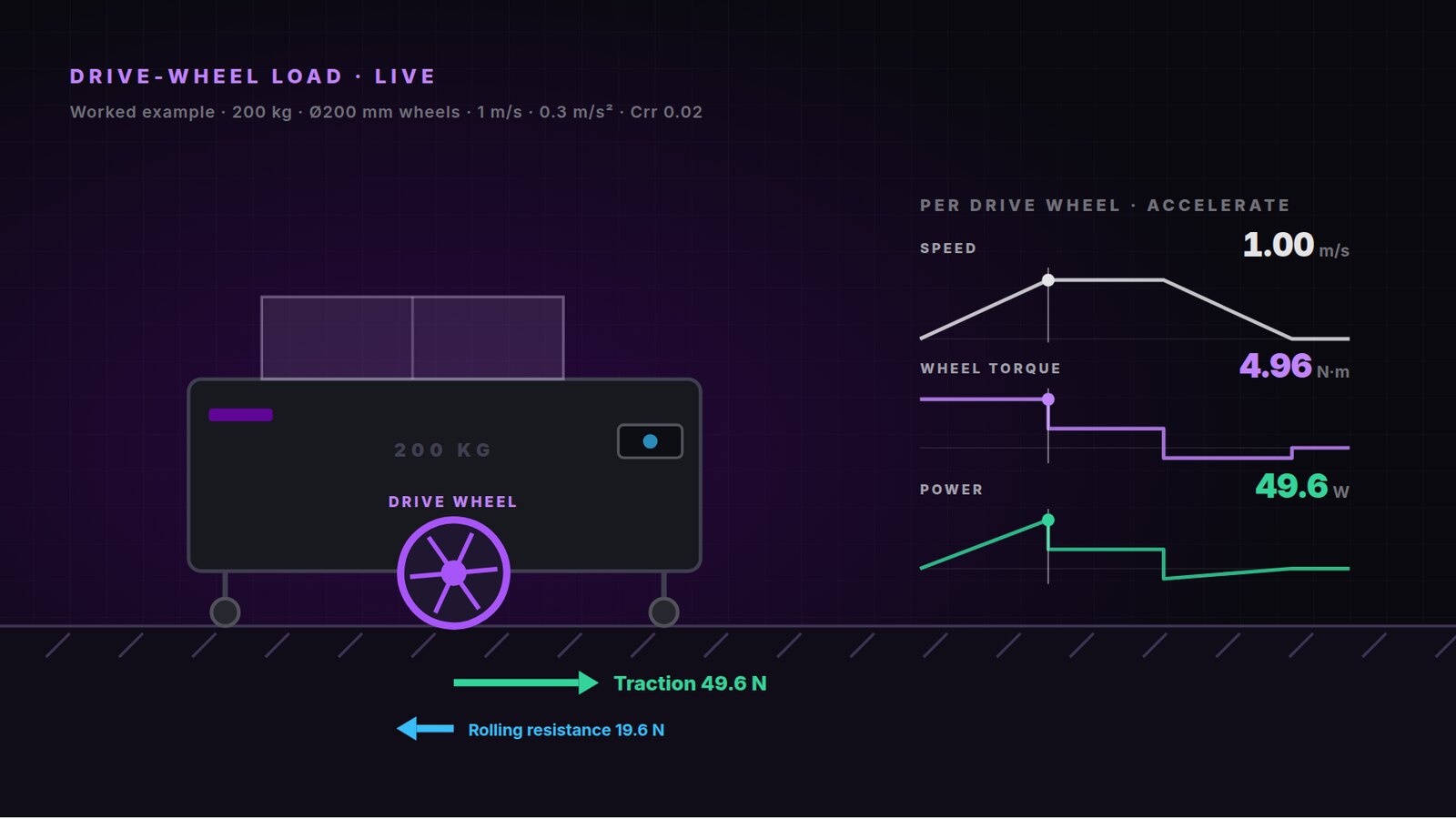
Selecting the right motor power is a critical step in designing an Autonomous Mobile Robot (AMR) or Automated Guided Vehicle (AGV). An undersized motor may struggle to accelerate the vehicle, climb slopes, or transport heavy loads. On the other hand, an oversized motor can increase system cost, weight, and energy consumption.
So, how do you calculate the motor power required for a drive wheel?
The answer depends on several factors, including the total vehicle mass, wheel diameter, target speed, acceleration, rolling resistance, floor conditions, and operating environment.
This article explains the fundamental equations for calculating drive-wheel motor power and shows how to use the results to select a suitable motor for AMR and AGV applications. Along the way, interactive figures let you change the inputs and see how each result responds.
1. Understand the Main Parameters
Before calculating motor power, engineers need to define the vehicle's operating conditions.
The main parameters include:
- Vehicle mass (m): The total mass of the robot, payload, batteries, and installed components, measured in kilograms (kg).
- Wheel radius (r): The radius of the drive wheel, measured in meters (m).
- Target speed (v): The desired vehicle speed, measured in meters per second (m/s).
- Acceleration (a): The required rate of speed increase, measured in meters per second squared (m/s²).
- Rolling resistance coefficient (Crr): A dimensionless value representing the resistance between the wheels and the driving surface.
- Road slope (θ): The inclination of the surface on which the vehicle operates.
- Number of driven wheels (n): The number of wheels that actively generate traction.
These parameters determine the tractive force required to move the vehicle and, consequently, the torque and power required from the motors.
2. Calculate the Required Tractive Force
The first step is to calculate the total force required to move the vehicle.
For a typical AMR or AGV, the required tractive force can be estimated using:
Ftotal = Frr + Facc + Fgrade
Where:
- Ftotal is the total required tractive force (N).
- Frr is the rolling resistance force (N).
- Facc is the acceleration force (N).
- Fgrade is the force required to overcome a slope (N).
2.1. Rolling Resistance Force
Rolling resistance is the force that opposes vehicle movement due to wheel deformation, floor conditions, bearings, and other mechanical losses.
For a vehicle operating on a relatively flat surface:
Frr = Crr × m × g
Where:
- Crr is the rolling resistance coefficient.
- m is the total vehicle mass (kg).
- g is gravitational acceleration, approximately 9.81 m/s².
A smooth industrial floor with suitable wheels generally produces less rolling resistance than a rough surface or one with unsuitable wheel materials.
The actual resistance should be estimated from wheel specifications or measured under representative operating conditions.
2.2. Acceleration Force
When the vehicle accelerates, additional force is required to increase its velocity.
The translational acceleration force is:
Facc = m × a
Where a is the desired linear acceleration in m/s².
For example, a heavier robot or a robot required to accelerate more quickly will need greater tractive force.
This equation describes the translational component. A more detailed design may also need to account for rotating wheel inertia, gearbox inertia, and drivetrain losses.
2.3. Slope-Climbing Force
When the robot travels uphill, the motors must overcome the component of gravity acting along the slope.
The required force is:
Fgrade = m × g × sin(θ)
Where θ is the slope angle.
For flat-floor applications, this component can be treated as zero. However, for robots that must climb ramps, the slope force may become a major part of the total motor load.
For a slope expressed as a percentage, the slope angle can be found using:
tan(θ) = slope (%) / 100
When the vehicle operates on uneven floors or must overcome obstacles, additional force margins may be necessary.
Interactive · Tractive force
Everything the drive wheels have to push against
Change the mass, acceleration, ramp and floor condition. The drive wheels must deliver a traction force equal to the sum of the forces resisting the motion.
Torque per drive wheel
4.96 N·m
For the article's AMR: r = 0.1 m, 2 wheels sharing the load equally.
3. Calculate the Required Torque at the Drive Wheel
Once the total tractive force has been determined, calculate the torque required at the wheel.
The equation is:
Twheel = Ftotal × r
Where:
- Twheel is the required torque at the wheel (N·m).
- Ftotal is the total tractive force (N).
- r is the wheel radius (m).
For example, if the total tractive force is 100 N and the wheel radius is 0.1 m:
Twheel = 100 × 0.1 = 10 N·m
Therefore, the wheel must generate approximately 10 N·m of torque under the assumed operating conditions.
If the vehicle has multiple driven wheels, the total force can be distributed between them. However, equal distribution should only be assumed when the mechanical design, weight distribution, traction, and control strategy support it.
For a system with two equally loaded drive wheels:
Twheel, per motor = Twheel, total / 2
This gives the required torque per wheel before considering transmission losses or other design factors.
4. Calculate the Required Motor Power
Motor power depends on both torque and rotational speed.
The mechanical power delivered at the wheel can be calculated using:
Pwheel = Ftotal × v
Alternatively:
Pwheel = Twheel × ω
Where:
- Pwheel is the mechanical power at the wheel (W).
- v is the vehicle speed (m/s).
- ω is the wheel's angular velocity (rad/s).
Wheel angular velocity can be calculated as:
ω = v / r
Combining these equations gives:
Pwheel = Twheel × v / r
If the wheel torque is expressed in N·m and angular velocity in rad/s, the result is in watts.
To convert watts to kilowatts:
Power (kW) = Power (W) / 1,000
Calculate Motor Power Per Wheel
If the vehicle uses multiple driven wheels, the power requirement can be distributed among the motors.
For n identical drive motors sharing the load equally:
Pwheel, per motor = Pwheel, total / n
This is an initial estimate. The actual motor rating must also account for drivetrain efficiency, duty cycle, thermal limits, acceleration requirements, and the motor's continuous and peak torque capabilities.
5. Practical Calculation Example for an AMR
Consider an AMR with the following operating parameters:
| Parameter | Value |
|---|---|
| Total vehicle mass | 200 kg |
| Number of driven wheels | 2 |
| Wheel diameter | 200 mm |
| Target speed | 1.0 m/s |
| Acceleration | 0.3 m/s² |
| Rolling resistance coefficient | 0.02 |
| Operating surface | Flat industrial floor |
| Gravitational acceleration | 9.81 m/s² |
For this example, assume that both drive wheels share the load equally and that wheel rotational inertia is excluded from the initial calculation.
Step 1: Calculate Rolling Resistance
Frr = 0.02 × 200 × 9.81
Frr = 39.24 N
Step 2: Calculate Acceleration Force
Facc = 200 × 0.3
Facc = 60 N
Step 3: Calculate Total Tractive Force
Because the vehicle operates on a flat surface, the slope force is zero.
Ftotal = 39.24 + 60
Ftotal = 99.24 N
Step 4: Calculate Required Wheel Torque
The wheel radius is:
r = 200 / 2 = 100 mm = 0.1 m
Therefore:
Twheel, total = 99.24 × 0.1 = 9.924 N·m
With two drive wheels sharing the load equally:
Twheel, per motor = 9.924 / 2
Twheel, per motor ≈ 4.96 N·m
This is the estimated wheel torque during the specified acceleration condition.
Step 5: Calculate Total Mechanical Power at the Target Speed
Pwheel, total = Ftotal × v = 99.24 × 1.0
Pwheel, total = 99.24 W
For two equally loaded drive wheels:
Pwheel, per motor = 99.24 / 2
Pwheel, per motor ≈ 49.62 W
The calculated mechanical power is approximately 50 W per wheel at the specified speed and acceleration.
However, this does not automatically mean that a 50 W motor is sufficient. The selected motor must also meet the required torque at the corresponding rotational speed, as well as the peak and continuous operating requirements.
Important Note About Acceleration
The example calculates the force required during acceleration at the target speed. At lower speeds, the motor may need to deliver substantial torque even though mechanical power is lower.
At constant speed on the same flat surface, acceleration force becomes zero. The steady-state tractive force would then be approximately 39.24 N, assuming the same rolling resistance coefficient.
For reliable motor selection, engineers should evaluate the entire operating cycle rather than using only one power calculation.
Interactive · Duty cycle
One move, three different answers
A single power figure hides how the load changes during a move. Follow the worked-example AMR as it accelerates, cruises, brakes and stops, and drag across the chart to read torque and power at any moment.
Peak torque
4.96 N·m
RMS torque
2.95 N·m
Peak power
49.6 W
Cruise power
19.6 W
Torque is highest from the moment the robot starts, about 1.7× the RMS torque the motor must sustain thermally. Power only peaks at the end of acceleration (49.6 W) and falls to 19.6 W in cruise. Check peak torque, continuous torque and speed separately.
6. Convert Wheel Speed to Motor Speed
Motor selection also requires checking the rotational speed needed to achieve the target vehicle speed.
The wheel's rotational speed in revolutions per minute (RPM) is:
RPMwheel = (60 × v) / (2 × π × r)
For the example above:
RPMwheel = (60 × 1.0) / (2 × π × 0.1)
RPMwheel ≈ 95.5 RPM
If the motor is connected directly to the wheel, it must operate at approximately 95.5 RPM to achieve a vehicle speed of 1.0 m/s.
If a gearbox is used, the motor speed will be higher according to the gear ratio.
For example, with a 10:1 reduction ratio:
Motor speed ≈ 95.5 × 10
Motor speed ≈ 955 RPM
A gearbox increases the available output torque while reducing output speed. Actual output torque depends on gearbox efficiency and the permitted load conditions.
For direct-drive integrated servo motors, the relationship between rated motor speed and the required wheel speed must be checked carefully. If the motor runs much faster than the wheel requires, a suitable transmission may be necessary.
7. Consider Efficiency and Safety Margins
The theoretical calculations provide a starting point, but real-world systems experience additional losses and variable operating conditions.
Drivetrain Efficiency
Motor power must be sufficient to cover mechanical power demand after accounting for transmission and drivetrain losses.
A simplified estimate is:
Pmotor, required = Pwheel / η
Where η is the overall mechanical efficiency, expressed as a decimal.
For example, if the required wheel power is 100 W and the overall efficiency is 85%:
Pmotor, required = 100 / 0.85
Pmotor, required ≈ 117.6 W
This estimate assumes that 85% represents the relevant overall efficiency between the motor shaft and the wheel. Electrical input power requires additional consideration of motor and drive efficiency.
Peak Torque and Continuous Torque
Peak torque is important during acceleration, starting, turning, and climbing. Continuous torque determines whether the motor can sustain the load without exceeding its thermal limits.
A suitable motor should meet both requirements over the intended duty cycle.
Battery Voltage and Current
For battery-powered AMRs and AGVs, the motor and drive must operate within the battery's actual voltage range.
Current demand should be checked during acceleration and other high-load events, not only during steady-state movement.
Battery capacity, wiring, connectors, protection devices, and regenerative braking behavior can also affect the overall design.
Operating Conditions
Real vehicles may encounter uneven floors, changes in payload, wheel wear, temperature variations, and temporary increases in rolling resistance.
A reasonable engineering margin can help accommodate these variations, but it should be based on the application rather than an arbitrary percentage.
8. How to Select a Suitable Servo Motor for an AMR or AGV
After calculating wheel torque, speed, and power, engineers can compare the results with the motor's performance specifications.
The key selection criteria include:
- Rated power: Must support the required operating cycle.
- Rated torque: Must meet the continuous torque requirement.
- Peak torque: Must cover acceleration, starting, and other transient loads.
- Rated speed: Must match the required wheel speed and transmission ratio.
- Supply voltage: Must be compatible with the battery and electrical system.
- Communication interface: Must match the robot controller, such as CANopen or EtherCAT where supported.
- Mechanical dimensions: Must fit the available mounting space.
- Brake requirements: Must suit the load-holding and stopping strategy.
- Thermal and environmental limits: Must support the intended operating conditions.
Saigon Dynamics offers integrated servo motor solutions for compact motion-control applications. For example, the ISL Series L-Shaped Servo All-in-One includes models in the 200–750 W power range, with 24–70 VDC supply compatibility and CANopen or EtherCAT options depending on the model.
These motors may be candidates for certain AMR and AGV designs, but the appropriate model should be selected by comparing the actual torque-speed requirements, duty cycle, and mechanical configuration with the manufacturer's specifications.
The calculator below runs the full procedure from this article and checks the result against the rated speed, rated torque, and peak torque of each ISL variant.
Interactive · Motor sizing calculator
From vehicle requirements to a servo motor
Enter your vehicle and drivetrain. The calculator works out tractive force, wheel torque and speed, converts them to the motor shaft through the gear ratio and efficiency, then checks every ISL variant. The smallest motor that passes is shown on the torque–speed chart; click a row to inspect another.
Vehicle
Drivetrain
| Requirement per motor | At wheel | At motor |
|---|---|---|
| Speed at target | 95.5 rpm | 1,910 rpm |
| Peak torque (accelerating) | 4.96 N·m | 0.292 N·m |
| Continuous torque (cruising) | 1.96 N·m | 0.115 N·m |
| Peak power | 49.6 W | 58.4 W |
| Cruise power | 19.6 W | 23.1 W |
2 driven wheels share the load, with a 20:1 reduction and 85% drivetrain efficiency.
Torque–speed check · ISL60 · 200 W · 48 VSmallest motor that passes
ISL60 · 200 W · 48 V covers this drive at 20:1. Cruising uses 18% of its rated torque, accelerating 15% of its peak torque, and the motor turns at 1,910 rpm.
| ISL motor · rated / peak torque | Speed | Cont. torque | Peak torque | Workable ratio | Result |
|---|---|---|---|---|---|
| ISL60 · 200 W · 24 V0.64 / 1.91 N·m · 3000 rpm | 64% | 18% | 15% | 3.6 – 31.4 | 24 V only |
| ISL60 · 200 W · 48 V0.64 / 1.91 N·m · 3000 rpm | 64% | 18% | 15% | 3.6 – 31.4 | Passes |
| ISL60 · 400 W · 48 V1.27 / 3.81 N·m · 3000 rpm | 64% | 9% | 8% | 1.8 – 31.4 | Passes |
| ISL60 · 600 W · 48 V1.91 / 3.81 N·m · 3000 rpm | 64% | 6% | 8% | 1.5 – 31.4 | Passes |
| ISL80 · 750 W · 48 V2.40 / 7.20 N·m · 3000 rpm | 64% | 5% | 4% | 1.0 – 31.4 | Passes |
Percentages show how much of each motor rating the drive would use at the selected gear ratio.
Explore the Saigon Dynamics Servo Motors product range to review available solutions.
Conclusion
Calculating motor power for a drive wheel involves more than reading a single wattage figure. Engineers must first determine the required tractive force, calculate wheel torque, establish the necessary rotational speed, and evaluate mechanical power under the intended operating conditions.
For AMR and AGV applications, the most important factors include total vehicle mass, wheel radius, target speed, acceleration, rolling resistance, slope, and drivetrain efficiency.
A systematic calculation helps engineers avoid undersized or unnecessarily large motors and provides a sound starting point for selecting a suitable servo motor.
Need help selecting a servo motor for your AMR or AGV? Visit Saigon Dynamics to explore integrated servo motor solutions for industrial automation.